Automatic Wheel Rim Line
The automatic wheel rim line is one of AMW’s flagship systems, developed through decades of experience in resistance welding, forming, and automated production equipment.
Using integrated welding and mechanical forming processes, the line converts flat steel sheet into high-quality steel wheel rims with consistent dimensional accuracy, short cycle times, and repeatable production quality. Each stage is engineered for automated operation, reducing manual variation while improving throughput, weld consistency, and finished rim reliability.
10-12” Steel Wheel Rim Line
70 - 180 mm width
1.8 -3.0 mm thickness
6 seconds / part @ 100% efficiency
13-18” Steel Wheel Rim Line
160 - 280 mm width
2.0 - 4.0 mm thickness
6 seconds / part @ 100% efficiency
Automatic Rim Wheel Line Machinery
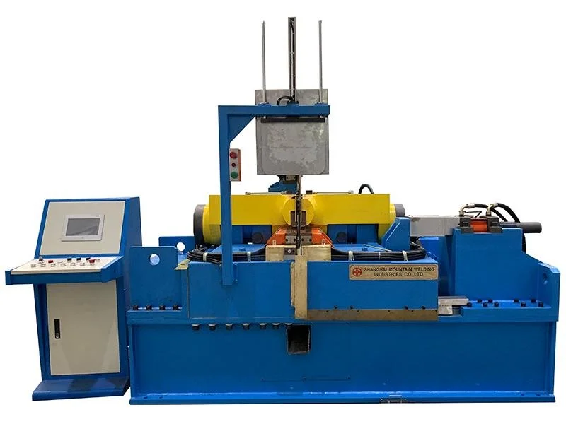
AC Butt Welding
A proven, cost-effective flash-butt welding platform for standard production where robust operation and simpler power architecture are priorities.
UNC-400
400 kVA power
250 mm min. diameter
320 mm max width
1800 mm² max cross section
500 kN clamping force
250 kN max upset force
UNC-800
800 kVA power
300 mm min. diameter
430 mm max width
2150 mm² max cross section
700 kN clamping force
350 kN max upset force
UNC-1000
1000 kVA power
500 mm min. diameter
650 mm max width
3750 mm² max cross section
800 kN clamping force
400 kN max upset force
UNC-1600
1600 kVA power
500 mm min. diameter
650 mm max width
4000 mm² max cross section
1200 kN clamping force
600 kN max upset force
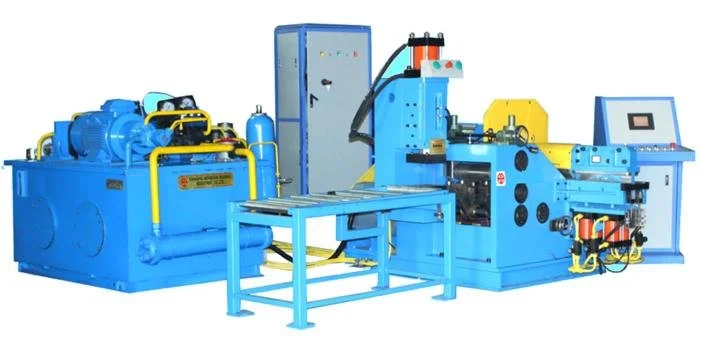
Marking, Coiling, and Flattening Machine
The marking, coiling and flattening machine forms coiled hoops from flat strips. A marking system has been integrated into the coiler at the machine’s feed section, and the coiled hoops are produced with a short, flat section on both sides of the gap, thus allowing for a weld to be produced using flat clamping and welding electrode.
10’-18’ Rim
10–18 in. rim diameter
4–8 in. rim width
220 mm minimum hoop diameter
2–5 mm rim thickness
320 mm maximum hoop width
7.5 kW motor power
11 kW hydraulic unit power
25 MPa maximum hydraulic pressure
16’-24’ Rim
16–24 in. rim diameter
3.5–13 in. rim width
300 mm minimum hoop diameter
2–5 mm rim thickness
430 mm maximum hoop width
11 kW motor power
15 kW hydraulic unit power
25 MPa maximum hydraulic pressure
22’-38’ Rim
22–38 in. rim diameter
7–20 in. rim width
400 mm minimum hoop diameter
5–10 mm rim thickness
650 mm maximum hoop width
15 kW motor power
18.5 kW hydraulic unit power
25 MPa maximum hydraulic pressure
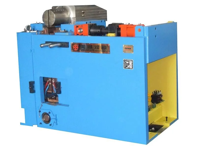
DC Flashless Butt Welding Machine
Clean, controlled DC upset welding for butt joints that need minimal material loss, reduced cleanup, and no flash burn-off.
UZC-750
750 kVA power
230 mm min. diameter
220 mm max width
800 mm² max cross section
400 kN clamping force
200 kN max upset force
UZC-1500
1500 kVA power
250 mm min. diameter
320 mm max width
1500 mm² max cross section
500 kN clamping force
250 kN max upset force
UZC-3000
3000 kVA power
450 mm min. diameter
500 mm max width
3000 mm² max cross section
800 kN clamping force
400 kN max upset force
UZC-4000
4000 kVA power
500 mm min. diameter
220 mm max width
3850 mm² max cross section
1000 kN clamping force
500 kN max upset force
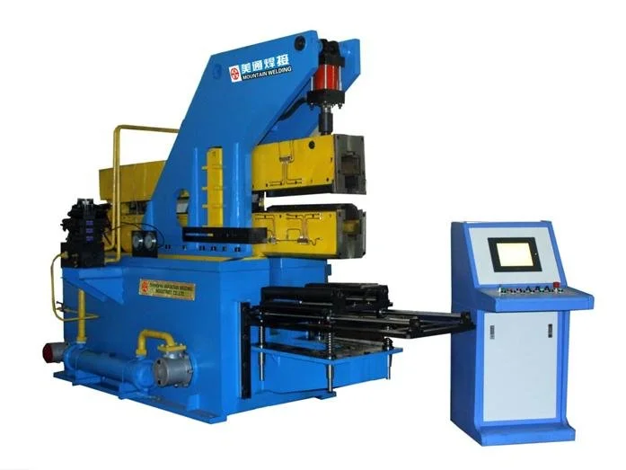
Trimmer and Planisher
5mm Width
5 mm max weld width
5 mm max weld height
3 planer tools
20 mm planer tool width
102 mm planisher roller diameter
12.5 T clamping force
12.5 T trimmer force
450 mm max hoop width
22 kW hydraulic station motor power
6mm Width
6 mm max weld width
7 mm max weld height
3 planer tools
25 mm planer tool width
102 mm planisher roller diameter
21 T clamping force
21 T trimmer force
650 mm max hoop width
30 kW hydraulic station motor power
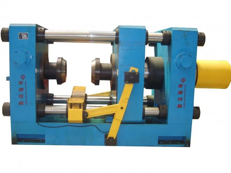
Flare Press
The flare press automatically expands welded hoops into the initial flared shape required for high-speed wheel rim profiling.
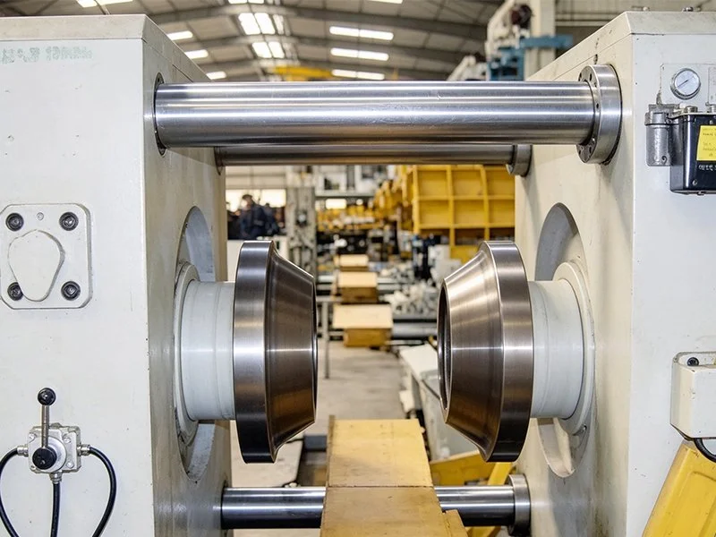
Specifications
10-32 inch diameter of flared hole
2-28 inch width of flared hole
Removes raised weld flash with precision planer tools, then rolls and compresses the joint to restore a smooth, uniform hoop profile for downstream forming.
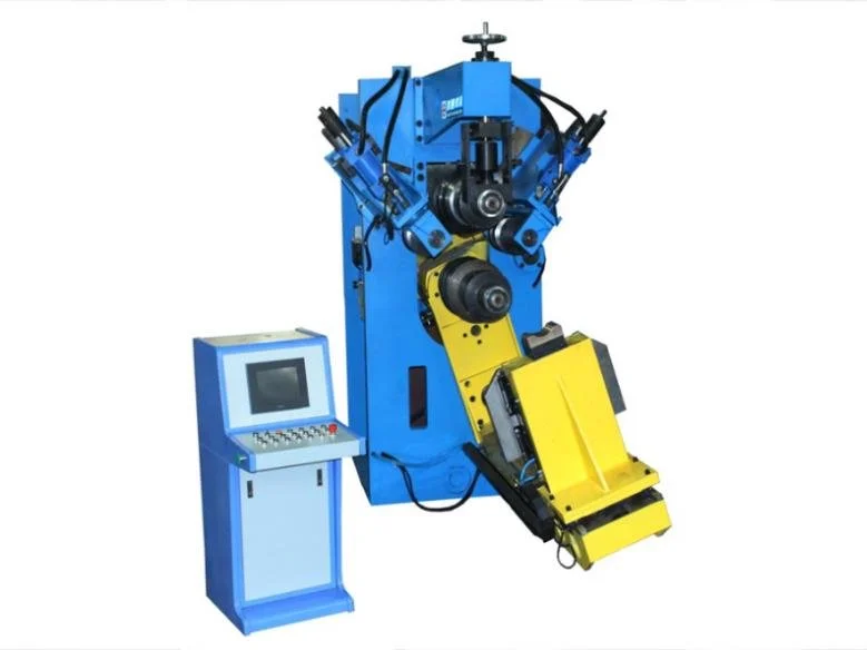
Roll Former
10’-14’ Diameter
2"–5" rim width
1.8–3.5 mm thickness
120 mm shaft diameter
1,400 Nm shaft torque
±2.6 mm lower shaft adjustment
2–10 mm/s lower shaft working speed
200 kN lower shaft lifting force
240 mm working distance between shafts
200 rpm shaft speed
12’-18’ Diameter
3.5"–13" rim width
2–5 mm thickness
150 mm shaft diameter
1,600 Nm shaft torque
±3 mm lower shaft adjustment
2–10 mm/s lower shaft working speed
266 kN lower shaft lifting force
270 mm working distance between shafts
130 rpm shaft speed
19.5’-38’ Diameter
5.25"–20" rim width
3–10 mm thickness
200 mm shaft diameter
2,250 Nm shaft torque
±5 mm lower shaft adjustment
2–10 mm/s lower shaft working speed
400 kN lower shaft lifting force
340 mm working distance between shafts
130 rpm shaft speed
The roll former uses powered shafts and precision tooling to progressively shape flared wheel hoops into the final rim profile across a wide range of sizes and material thicknesses.
Expander and Press
The expander and press system enlarges welded rim blanks to the required diameter, then sizes and shapes them under controlled force for accurate final dimensions.
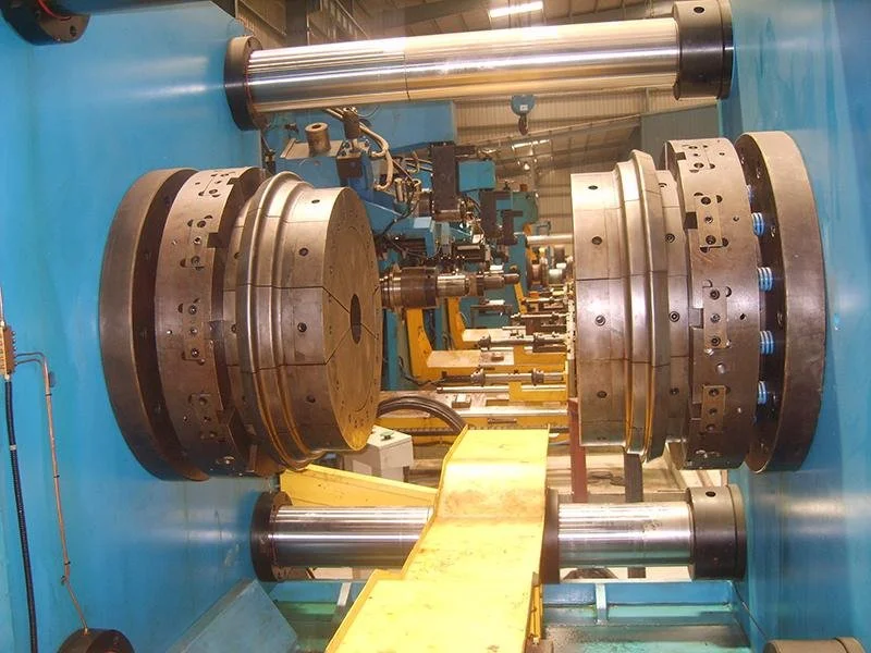
Specifications
10-32 inch expander diameter
2-28 inch expander width
Options:
100 Ton Press
200 Ton Press
300 Ton Press
500 Ton Press
Flow Former
Specifications
450–630 mm spinning blank diameter
8–16 mm spinning blank thickness
450–680 mm spinning part diameter
140 mm maximum spinning part height
450–300 r/min main shaft speed
200 kW main shaft power
30,000 kg machine weight
The roll former uses powered shafts and precision tooling to progressively shape flared wheel hoops into the final rim profile across a wide range of sizes and material thicknesses.
Multi Spiral Coiler for Side Ring Bar
Specifications
800 mm² maximum rolled-part cross section
508 mm minimum rolled-part diameter
610 mm maximum rolled-part diameter
290 mm minimum distance between upper and lower rollers
70 mm upper roller adjustment range
800 mm workpiece feeding position
13.1 r/min lower roller speed
22.31 r/min upper roller speed
Ø140 × 100 mm lower roller dimensions
Ø90 × 90 mm upper roller dimensions
18.5 kW Y200L1-6 motor power
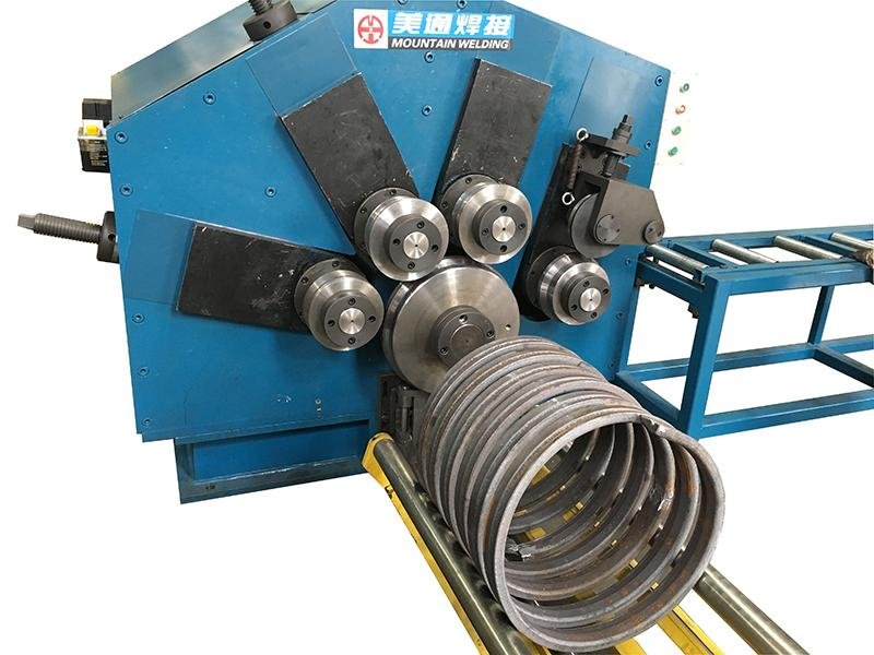
The multi-spiral coiler continuously bends side-ring bar stock into uniform helical coils for efficient production of multiple ring blanks.
Multi-Spot Welding Machine
Specifications
Four-spindle spot welder for steel wheel rims
24 equally spaced weld points
20-second machine cycle, including loading and unloading
4 × 63 kVA transformer capacity
50% duty cycle
75 mm minimum electrode stroke
600 kgf electrode force at 0.5 MPa
Siemens PLC control
Miyachi Model 210 or 110 weld controller
Driven indexing fixture with cam-operated rotation
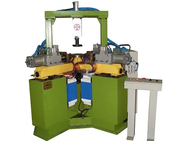
The multi-spot welding machine automatically indexes and welds 24 evenly spaced points around a steel wheel rim using four synchronized welding heads.
Videos
Cut-to-length
Coiler + Butt Welding + Trimmer + Plannisher + Edge Nipper + Reround
Coiler + Flattener + Butt Welding
Expander
Trimmer + Plannisher + Edge Nipper + Reround + Flare
Roll Former + Expander
Air Leakage Test + Valve Hole + Disc Assembling Press
Coiler + Flattener + Butt Welding
Air Leakage Test
Disc Assembling Press
Disc Assembling Press
Calibration
Calibration to Run Out Test
Run Out Test
Customer List
Maxion
AMW
Zhenxi Wheel
Xinming Wheel
Baosteel Wheel
Accuride
Yulu Wheel
Anyang Wheel
Carrier Wheels
Klassic Wheels
SSWL
Bhagawati Group
SWW